Next: 3.3.4 Calling of module MA2D3E Up: 3.3 Extrusion method (cylindrical topology) Prev: 3.3.2 Simplified version Index Contents
![]()
![]()
![]()
![]()
![]()
![]()
![]()
![]()
![]()
Next: 3.3.4 Calling of module MA2D3E
Up: 3.3 Extrusion method (cylindrical topology)
Prev: 3.3.2 Simplified version
Index
Contents
Consider a 2D mesh which will either serve as the lower section, or be used to define this section.
One section being formed, we can deduce other sections from it. The layers of 3D elements will then be formed by connecting the sections defined previously, two-by-two.
Let:
The basis, or lower section, is section 0, the sections being numbered from 0 to n. The layers are numbered from 1 to n, layer i linking sections i-1 and i. Furthermore, vertical, horizontal, etc., items are called so with reference to a classical cylinder positioned on the plane z=0, thus relative to the topology of the domain.

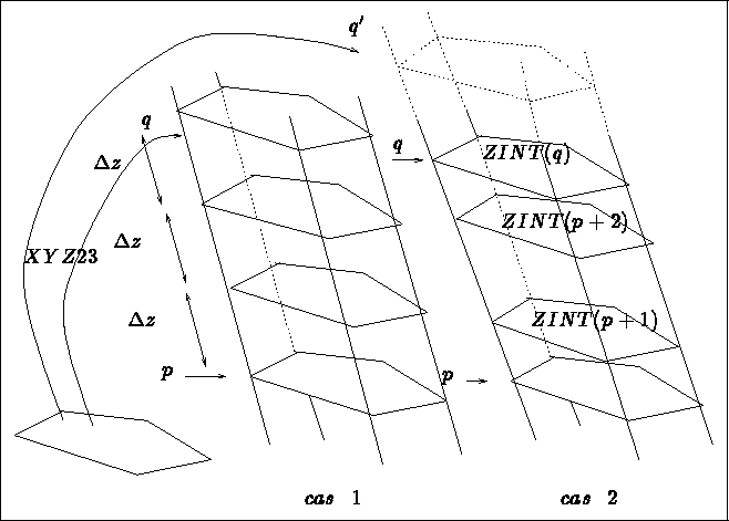
Figure 3.9: The basis as the image of the 2D mesh (2 cases)


Figure 3.10: Sections p to q as the image of the 2D mesh


We therefore have 3 possibilities in this case:

Figure 3.11: Sections p to q as interpolated between 2 sections
(2 cases)
Summary: The basis is constructed like a 2D mesh with a side given, or like the transformations of a 2D mesh via XYZ23.
The sections are deduced from the 2D mesh via XYZ23, interpolated between two extreme sections with sides equidistant or given, the one deduced from the other, step by step, via XYZ33 or MAT.
The different methods could also be combined.
One layer is defined by 2 consecutive sections. The constituent elements of the layer are created by connecting the corresponding points. In practice, at the time that at least 2 sections have been created, we create at least 1 layer in parallel.
It is possible to identify the points, edges and faces of the basis and the upper section of the cylinder for the case where the latter is closed (option COLLER).
Certain transformations (for example rotation) can generate degenerate elements (when the rotational axis is supported by an edge of the initial mesh). In this case, the elements created are no longer the natural correspondents of the 2D elements (an automatic operation performed by the module).
Certain transformations (for example rotation) can generate degenerate elements (when the rotational axis is internal to the mesh). In this case, the elements created are no longer the natural correspondents of the 2D elements (option RAPIDE).
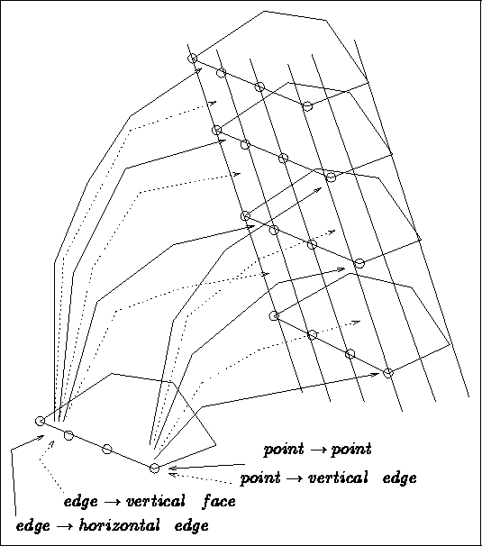
The physical attributes (sub-domains and references) of the 3D mesh are generated using the numbers present in the initial 2D mesh. This correspondence indicates:
 becomes
Let NBDES be the number of descriptions to assign, then
for I=1,NBDES we give for five values:
 ,
,  , TYPE,
  ,
,  defined in array DESREF(5,NBDES) by:
 )
)
 )
)
 3D sub-domain number
 3D horizontal faces reference
 3D vertical faces reference
 3D horizontal edges reference
 3D horizontal edges and vertical faces reference
 3D vertical edges reference
 3D points reference
 3D points and vertical edges reference
 ) to all the items (faces, edges and points) of a given section
(
 )
)
 )
)
 ) to associate to the items 3D deduced from the 2D items having
the above number,
  , as attribute

Figure 3.13: The transfers and physical attributes
Note that, in the same way, we can completely define all the items of the 3D mesh: points, sides and faces whatever their position may be (see figure 3.13).
Important remark: The assignments are done in the order of their description (there is no commutation; a request given supersedes a request prescribed beforehand).