Next: 3.2.2 Calling of module COLIB2 Up: 3.2 Multi-block method Prev: 3.2 Multi-block method Index Contents
![]()
![]()
![]()
![]()
![]()
![]()
![]()
![]()
![]()
Next: 3.2.2 Calling of module COLIB2
Up: 3.2 Multi-block method
Prev: 3.2 Multi-block method
Index
Contents
The multi-block method , [George-1989d] and [George-1991], generates a mesh of a two- or three-dimensional domain from a structured splitting (by an algebraic method) of a coarse mesh of this domain. This mesh consists of an assembly of geometrically standard blocks (segment, triangle, quadrilateral, tetrahedron, pentahedron, hexahedron) on the sides on which control points are given. The control points determine, on one hand, the geometry of the domain in terms of their position and, on the other hand, the fineness of the splitting and therefore the size of the elements of the final mesh. They must be equal, in number, on 2 logically connected sides.

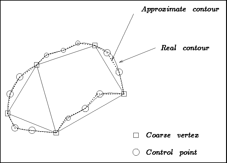
Figure 3.1: Domain, initial blocks and approximate domain
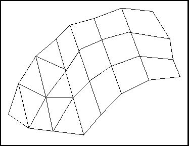
Figure 3.1 shows the domain under consideration, the coarse meshing into 2 blocks and its approximation by the given control points. Note that the number of points on the connected sides are the same. Figure 3.2 exhibits the result obtained.

Figure 3.2: Mesh of the domain obtained from the description given
The principal steps of the method are given below:
The data corresponding to the coarse vertices defines the blocks of the coarse mesh. The latter is input in R³ (to obtain a R² mesh we fix side z to the value 0 by indicating that we only want to store the abscissa and ordinates, in the case of blocks of type: segment, triangle and quadrilateral; if not, a surface mesh is obtained which is coarsely described via these triangular or quadrilateral blocks).
The coarse mesh must fulfill the usual conditions of conformity.
The list of vertices defining the blocks obeys certain rules:
The control points enable us to define the real geometry of the block better. They also indicate the number of subdivisions of the splitting to be done. The following rules must by respected:
 points on sides 1 and 3, and
  points
on sides 2 and 4 (these 2 values are independent)
 on the edges of the triangular faces and an independent value
 on the remaining edges
 , corresponding to the opposite edges
The edges are split into sub-segments joining the control points (created by a module or entered explicitly). A global numbering is allocated to these points.
The edge points of the faces are mapped, according to their type, onto a unit triangle or quadrilateral
while respecting their respective positions; the unit face is meshed in a canonical fashion and this mesh is
projected onto the real face.
Let  be a point in the preceding canonical mesh, with coordinates
  and
and  ,
then for a face analogous to a triangle, the following transformation is used:


where  designates vertex i of the real face, and
  is a parametrization of side i of the same
face.
In the case of a face analogous to a quadrilateral, the following transformation is used:


The points obtained at this stage (coarse points, control points of the edges and points on the faces) enable us to apply the same method to blocks. For each block, the collection of these points is projected onto the unit block with corresponding geometry. The latter is meshed in a canonical fashion and then projected onto the real block. The numbers corresponding to the vertices created is constructed with the aid of a global pointer, associated to the triple, i, j, k, giving the position of the point in the block whose value depends on the block treated.
The final mesh is obtained as the union of the meshes of the different blocks (the gluing together is automatic as the interfaces (points, edges and common faces of 2 blocks) have been meshed using a global numbering).
The physical attributes of the items created are as follows:
Remarks: