Next: 5.3.2 Construction of a three-dimensional mesh Up: 5.3 A three-dimensional example Prev: 5.3 A three-dimensional example Index Contents
![]()
![]()
![]()
![]()
![]()
![]()
![]()
![]()
![]()
Next: 5.3.2 Construction of a three-dimensional mesh
Up: 5.3 A three-dimensional example
Prev: 5.3 A three-dimensional example
Index
Contents

Figure 5.4: Explanatory cut through the geometry
The domain is, topologically speaking, a cylinder. Consequently, the mesh data of one of the sections is sufficient for the construction of the 3D mesh sought.
Figure 5.4 shows a semi-cut in the symmetry plane of the domain. It allows us to see how we should define the progression of the 2D mesh and indicates how to define the different sections. We thus have successively:
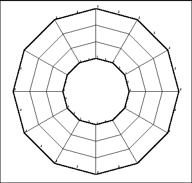
The data is used to create the 2D mesh of a representative section (via module APNOPO and its preprocessor APNOXX). The mesh obtained is shown in figure 5.5.
'TEST_1_MA2D3D                                                       '
 COURBES
     1                                 $ IMPRE
 COURBE01(X,Y)=
       X*X+Y*Y-4.;
 COURBE02(X,Y)=
       X*X+Y*Y-25.;
FIN
'POINTS                                                              '
     1     5                            $ IMPRE NPOINT  $
$   NOP   NOREF(NOP)     X(NOP).            Y(NOP).  $
     1       1         -.200000E+01     0.000000E+00
     2       1         0.200000E+01     0.000000E+00
     3       2         0.500000E+01     0.000000E+00
     4       2         -.500000E+01     0.000000E+00
     5       0         0.000000E+00     0.000000E+00
'LIGNES                                                              '
     1     4                            $ IMPRE  NDLM   $
$   NOLIG NOELIG NEXTR1 NEXTR2 NOREFL NFFRON       RAISON $
       1      7      2      1      1     -3     0.100000E+01
       5                                $ NOCE
       2      4      2      3      0      0     0.100000E+01
       3      7      3      4      2     -3     0.100000E+01
       5                                $ NOCE
       4      4      4      1      0      0     0.100000E+01
'QUAC                                                                '
     1     0     1     4    -1          $ IMPRE NIVEAU NUDSD NBRELI NS1L
 $ LIST OF CONTOUR LINES :
     1     2     3     4
     7     1                            $ IMAX NQUAD
'SYMD                                                                '
     1     0     2                      $ IMPRE NIVEA1 NIVEA2
     0     0                            $ NBNNF NBNNSD
  0.00000E+00  0.10000E+01  0.00000E+00 $ A. B. C.
'RECO                                                                '
    1    0    2    1  0.10000E-02    1  $ IMP NIV1 NIV2 NIV3 EPS IOPT
     0     0                            $ NBNNF NBNNSD
'SAUV                                                                '
     1     1     0                      $ IMPRE NINOPO NTNOPO
 rocket2d.nopo
 $ FILE NAME
'FIN                                                                 '

Figure 5.5: The 2D starting mesh