Next: 4.3 3D transformations Up: 4 Creating a 3D image Prev: 4.1 General program structure Contents
![]()
![]()
![]()
![]()
![]()
![]()
![]()
![]()
Next: 4.3 3D transformations
Up: 4 Creating a 3D image
Prev: 4.1 General program structure
Contents
The visualization surface on which the 3D image will be displayed is defined, as in the 2D case, by FENTR2 or RFENTR. The management of the clipping indicators is, as in 2D, defined by CLIP and CLIPHD.
As in the 2D case, it corresponds to defining a zone where the object is described. Clearly, a plane mask must be used to define a 3D object.
The most usual case corresponding to a perspective view is described here , while the other cases will be described later on.
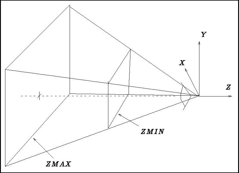
Figure 4.1: Pyramid of vision and depth limitation
For a perspective view , the MASK is in fact a pyramid of vision (figure 4.1) with a rectangular base and where the observer's eye is positioned at the vertex.
In principle, this pyramid is infinitely long, but it can be limited in depth by two planes which are perpendicular to the vision axis. As in the 2D case, only the part found inside this space will be visible.
      SUBROUTINE PRSPCT(ALPHA, BETA)
      REAL ALPHA, BETA
This procedure defines a perspective with half-angle vision of ALPHA in X and BETA in Y, for an observer positioned at (0., 0., 0.) in his own coordinate system and looking in the negative Z direction.
In addition, it deduces a 2D mask which could be defined elsewhere by:
CALL MASQU2(-TAN(ALPHA), TAN(ALPHA), -TAN(BETA), TAN(BETA))
The mask corresponds to a rectangle obtained by the intersection of the vision pyramid with the plane (Z = -1). In this mask we can, if so wished, plot objects in 2D (projections of the object onto this plane for example). In reality, FORTRAN 3D calculates the object's position in the 3D space and plots its projection onto this mask.
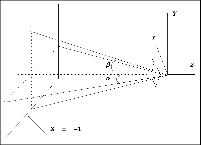
Figure 4.2: 2D mask deduced by calling PRSPCT
Let us note immediately that we always associate a coordinate system with the observer such that his/her eye is positioned at (0., 0., 0.) and he/she looks in the negative Z direction. This coordinate system is independent of the object's. In the following paragraph, we will see how to obtain this normalized position.
      SUBROUTINE MASQU3(ZMIN, ZMAX)
      REAL ZMIN, ZMAX
When using PRSPCT, ZMIN and ZMAX are the distances with respect to the observer of the two planes which are parallel to the "X0Y" plane in the observer's coordinate system. The observer will always be in the normalized position described above. Only the part of the image which lies between the two planes will be displayed. The clipping in depth, mentioned earlier, is therefore performed.
As in the 2D case, it is possible to suppress the clipping defined by the above two subroutines during execution of a program. This suppression can be either momentary or definitive.
     SUBROUTINE CLIP3(FCONE, FMASQU)
     LOGICAL FCONE, FMASQU
This subroutine is used to assign , or not, the preceding clipping according the the values of FCONE and FMASQU.
Subroutine PRSPCT , as mentioned earlier, defines a perspective (amongst other things!). It could be desirable in certain applications to remove this perspective effect, at least momentarily:
      SUBROUTINE NOPERS(FLAG)
      LOGICAL FLAG
This subroutine is used to avoid taking the perspective, defined by PRSPCT, into account. If FLAG = .TRUE., this perspective and the implied clipping are not effected. FLAG is set to .FALSE. on exit from PRSPCT.
A window in 3D is defined in the same manner as in 2D. The same subroutines are valid here. The window contains the image falling inside the 2D mask computed by subroutine PRSPCT .
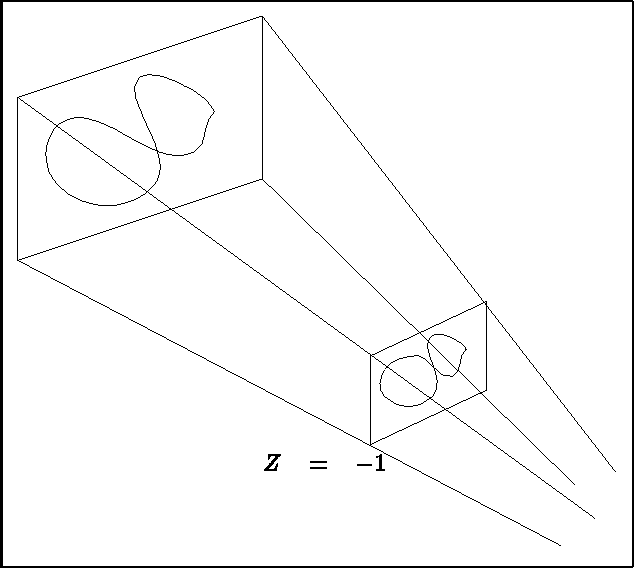
Figure 4.3: Mask and window correspondence for a 3D object