Next: 4.5 3D graphics instructions Up: 4 Creating a 3D image Prev: 4.3 3D transformations Contents
![]()
![]()
![]()
![]()
![]()
![]()
![]()
![]()
Next: 4.5 3D graphics instructions
Up: 4 Creating a 3D image
Prev: 4.3 3D transformations
Contents
As seen before, it corresponds to first of all positioning the observer with respect to the object. In case of stacking PUSHes and PULLs, it corresponds to positioning an object with respect to another.
Let us take an example: Suppose that we construct the following object composed of two separate objects: PIECE A, a cube with center of gravity 'O' and PIECE B, a cylinder glued onto one of its faces. We can proceed with its description in two different ways:
However, in both cases, we must first position the observer with respect to the object.
Let us adopt the following vocabulary:
A very simple manner to position the observer in the initial space is to use the following subroutine:
      SUBROUTINE NRMLST(XO, YO, ZO, XR, YR, ZR, IVERTI)
      REAL XO, YO, ZO, XR, YR, ZR
      INTEGER IVERTI
where:
(XO, YO, ZO) is the position of the observer in the initial coordinate system;
(XR, YR, ZR) represent the coordinates of the point viewed in the same coordinate system;
IVERTI is the vertical of the initial coordinate system, such that:
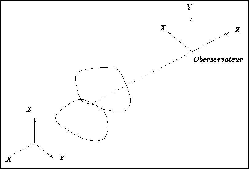
We can thus associate a local coordinate system with the observer so that he/she is positioned at its origin, looking in the negative Z direction. This is the normalized position of which we spoke earlier.
Subroutine NRMLST is generally used in conjunction with "PRSPCT".

Figure 4.4: Coordinates corresponding to the observer
The various transformations that can be applied to the called objects are listed below:
      SUBROUTINE TRSL(A, B, C)
      REAL A, B, C
defines a translation of the called object by a vector (A, B, C) with respect to the calling object.??
      SUBROUTINE ROT(I, ALPHA)
      INTEGER I
      REAL ALPHA
defines a rotation of the called object of an angle ALPHA radians around an axis I, where the positive direction is the trigonometric direction. The axis numbers are given by:
      SUBROUTINE ROTAXE(PX, PY, PZ, VX, VY, VZ, THETA)
      REAL PX, PY, PZ, VX, VY, VZ, THETA
defines a rotation of the called object of an angle THETA radians around the axis defined by the vector with origin (PX, PY, PZ) and components (VX, VY, VZ).
      SUBROUTINE SYMTRI(I, J)
      INTEGER I, J
defines a symmetry of the called object:
      SUBROUTINE SCALE(A, B, C)
      REAL A, B, C
defines a scale change of the called object along axis OX by a factor A, OY by a factor B and OZ by a factor C.
      SUBROUTINE SHEAR(A, B, C)
      REAL A, B, C
defines a shearing, i.e. the following transformation:
      X' =   X + B*Y + C*Z
      Y' = A*X +   Y + C*Z
      Z' = A*X + B*Y +   Z
      SUBROUTINE POS3D(P1, P2, P3, Q1, Q2, Q3)
      REAL P1(3), P2(3), P3(3), Q1(3), Q2(3), Q3(3)
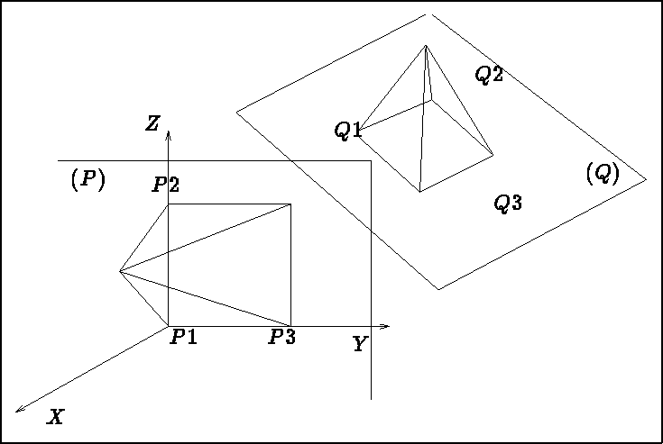
where P1, P2 and P3 are the three points in the called object's space , and Q1, Q2 and Q3 are three points in the calling object's space (thus, the above two sets of three points each define a plane in the 3d space).
This transformation enables the user to superpose two planes (and thus position the called object with respect to the calling object) in the following manner:

Figure 4.5: Transformation contained by calling subroutine POS3D
Another subroutine exists which enables the user to define his own transformation himself by inputting
his own transformation matrix. The latter is a 4 4 matrix whose structure is described in the chapter
dealing with internal subroutines.
     SUBROUTINE TRANSF(MAT)
     REAL MAT(4, 4)
defines a transformation via matrix MAT in homogeneous coordinates (see Chapter 7 dealing with internal subroutines for the matrix structure).