Next: 3.3.2 Simplified version Up: 3.3 Extrusion method (cylindrical topology) Prev: 3.3 Extrusion method (cylindrical topology) Index Contents
![]()
![]()
![]()
![]()
![]()
![]()
![]()
![]()
![]()
Next: 3.3.2 Simplified version
Up: 3.3 Extrusion method (cylindrical topology)
Prev: 3.3 Extrusion method (cylindrical topology)
Index
Contents
This method enables us to construct a mesh of all domains with a cylindrical topology from a 2D reference mesh by stacking layers of 3D elements. The nature of the 3D elements is deduced from that of the 2D elements of the reference mesh.
In fact, all domains which are possible to define in this fashion are said to be topologically cylindrical.
The data corresponding to this mesh generator is therefore the 2D mesh of a reference section and the definition of the sections along the generating axis.

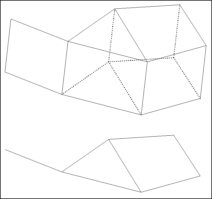
Figure 3.8: Correspondence 2D - 3D
This method is known as the translation-stacking method or extrusion method.
Segments in the space are associated to the points of a 2D mesh, quadrangular layers in the space are associated to the segments in the 2D mesh, pentahedra are associated to the triangles, and hexahedra are associated to the quadrilaterals. The connectivity is deduced from that of the two-dimensional basis mesh and from the section index.
In order to be able to treat domains containing the axis of the associated cylinder, it is necessary to consider the cases of possible degeneracy (see example), such as a quadrilateral giving rise to the creation of pentahedra and not hexahedra.
As input data, this mesh generator requires a two-dimensional mesh of a section representing the domain and the definition of a transport function for this section used to define the set of layers for the stacking to be realized.
The efficiency of this method results form several possibilities offered to define the coordinates of the vertices of the sections, either directly from the 2D basis mesh, or section by section from the definition of a starting section. A 3D vertex is known by the 2D vertex from which it is deduced as well as its sectional index, k. Consequently, it suffices to input, according to the case under consideration, the following data:
The face, edge and point references of the mesh created are defined by the user, as well as the sub-domain numbers of the elements created; these values are deduced, according to a given correspondence (see below), from the values present in the initial mesh.