Next: 3.4 Three-dimensional solutions TRC3XX Up: 3 Visualization of solutions Prev: 3.2 Two-dimensional solutions TRMCXX Contents
![]()
![]()
![]()
![]()
![]()
![]()
![]()
![]()
Next: 3.4 Three-dimensional solutions TRC3XX
Up: 3 Visualization of solutions
Prev: 3.2 Two-dimensional solutions TRMCXX
Contents
Preprocessor TRSTXX is used to visualize meshes and the corresponding stresses for a two-dimensional elasticity problem. The stresses are contained in a TAE data structure obtained by combining the solutions (displacements) with the element stresses computed at the same time as the element matrices and right-hand-sides (see part 1 of this user guide).
The module is used to visualize the stresses as follows:

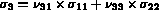
and in the case of plane deformations:

where 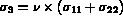 for the isotropic case, and
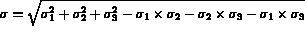
 for the orthotropic case. The
purely anisotropic case is not considered.
for the orthotropic case. The
purely anisotropic case is not considered.
and in the case of plane deformations:
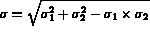
where  is defined above.
The user can also visualize the plastic zones when considering a plastic problem. In this case, the Von-Mises or Drucker-Prager criterion is used to determine the plastic zones.
In addition, the user can also visualize the temperatures and flux obtained when considering a thermal problem with mixed finite elements. The temperatures or flux are contained in a TAE data structure obtained by combining the solutions (flux or temperatures) with the element temperatures or flux computed at the same time as the element matrices and right-hand-sides (see part 1 of this user guide).
In practice, we use preprocessor TRSTXX to indicate to the module the different choices made from the possibilities offered.
The module computes the extrema corresponding to the mesh and solution automatically so that the corners of the box in which the plot will be displayed can be defined.
The menu of TRSTRE (module called to visualize the stresses or plastic zones) is shown below: To visualize the temperatures or flux, module TRFLUX is used (see further down).
 --------------------------------------------------------
 | 10 | PLOT TYPE                 |  MESH ONLY
 --------------------------------------------------------
 | 11 | DEVICE NUMBER             |       1
 --------------------------------------------------------
 | 12 | PLOT TITLE                |
 --------------------------------------------------------
 | 20 | D.S. MAIL TO PLOT         |  carre.mail
 --------------------------------------------------------
 | 20 | D.S. COOR TO PLOT         |  carre.coor
 --------------------------------------------------------
 | 31 | QUESTIONS ABOUT A D.S.    |   NO
 --------------------------------------------------------
 | 30 | PLOT SIZE                 |  AUTO
 --------------------------------------------------------
 | 40 | CHARACTER TYPE            |  HARD
 --------------------------------------------------------
 | 50 | ITEMS TO PLOT             |  TRIANGULATION
 --------------------------------------------------------
 | 60 | LEGEND                    |  YES
 --------------------------------------------------------
 | 70 | NUMBER                    |  NONE
 --------------------------------------------------------
 | 80 | LINE TYPE (MESH)          |  SOLID
 --------------------------------------------------------
A default value is proposed for each option. By default, only the mesh is visualized. To view the stresses, plastic zones, flux or temperatures as well, key 10 must be selected. The above table lists the selections made automatically. Type 0 to obtain a plot.
A key (a number) and a status correspond to each item. To modify the status, it suffices to type the key and enter the values corresponding to the status desired (see the general introduction). The list of keys is given below:
  -- MESH
     NOTHING                 : 0
     TRIANGULATION           : 1
     GEOMETRIC BOUNDARY      : 2
     REFERENCED BOUNDARY     : 3
     SHRINK                  : 4  ?
The shrink operation consists of contracting, by a given ratio (0.8 by default, value
modified via key 23), each element with respect to its barycentre.
    NO NUMBER          : 0
    ELEMENT : 1 - POINT: 2 - NODE  : 3
    SUBDOMAIN          : 4
    REFERENCE (ALL)    : 5
    REFERENCE POINTS   : 6 - NODES : 7
    REFERENCE EDGES    : 8
    SOLID      : 1  --   DOTTED    : 2
    DASHED     : 3  --   MIXED     : 4 ?
Once a plot is displayed on the screen, a graphics menu appears, as for the other modules, which allows us to:
We now give some details regarding the choices possible as a function of the type of visualization selected:
This corresponds to the case described above (identical with respect to the possibilities offered by preprocessor TRNOXX for the two-dimensional case, to which the user is referred).
Activate key 10 and choose option 1. It is then necessary to enter the name of the file containing D.S. TAE containing the stresses. The enlarged menu (additional keys followed by an asterisk) is given below:
 ------------------------------------------------------------
 | 10 | PLOT TYPE                 |  MESH AND STRESSES
 ------------------------------------------------------------
 | 11 | DEVICE NUMBER             |       1
 ------------------------------------------------------------
 | 12 | PLOT TITLE                |
 ------------------------------------------------------------
 | 20 | D.S. MAIL TO PLOT         |  carre.mail1
 ------------------------------------------------------------
 | 20 | D.S. COOR TO PLOT         |  carre.coor1
 ------------------------------------------------------------
 | 21 | D.S. TAE USED             |  carre.taes
 ------------------------------------------------------------
 | 24 | LOAD CASE                 |       1
 ------------------------------------------------------------
 | 33 | CRITERION TO PLOT         |   PRINCIPAL STRESSES
 ------------------------------------------------------------
 | 28 | ARROW ENDS                |      -1
 ------------------------------------------------------------
 | 29 | BIGEST ARROW IN CM.       |     2.000000
 ------------------------------------------------------------
 | 31 | QUESTIONS ABOUT A D.S.    |   NO
 ------------------------------------------------------------
 | 30 | PLOT SIZE                 |  AUTO
 ------------------------------------------------------------
 | 40 | CHARACTER TYPE            |  HARD
 ------------------------------------------------------------
 | 50 | ITEMS TO PLOT             |  TRIANGULATION
 ------------------------------------------------------------
 | 60 | LEGEND                    |  YES
 ------------------------------------------------------------
 | 70 | NUMBER                    |  NONE
 ------------------------------------------------------------
 | 80 | LINE TYPE (MESH)          |  SOLID
 ------------------------------------------------------------
 | 80 | LINE TYPE (STRESSES)      |  SOLID
 ------------------------------------------------------------
A default value is proposed for each option. The above table lists the selections made automatically when plotting the stresses. Type 0 to obtain the plot of the mesh.
A key (a number) and a status corresponds to each item. To modify the status, it suffices to type the key and enter the values corresponding to the status desired (see the general introduction). The list of keys is given below:
    PRINCIPAL STRESSES            : 1
    TRESCA CRITERION              : 2
    VON MISES CRITERION           : 3
    VON-MISES PLASTIC ZONE        : 4
    DRUCKER-PRAGER PLASTIC ZONE   : 5 ?
   EXTREMITY OPEN , NORMALISED : -1
   EXTREMITY CLOSED , NORMALISED  :  1
   EXTREMITY OPEN , FIXED      : -2
   EXTREMITY CLOSED , FIXED       :  2
The arrowhead is open (2 lines) or closed (a triangle), and its "length" is calculated as a function of the size of the arrow (which is related to the velocity modulus) or fixed (for all the arrows) to a value specified by the user.
    SOLID      : 1  --   DOTTED    : 2
    DASHED     : 3  --   MIXED     : 4 ?
When visualizing a criterion (via key 33), it is plotted by hatching (defined by key 27 with respect to the density), or in color.
 , and the nature (isotropic, etc.) of the material, information which
is not stored in the D.S. Consequently, this information must be entered here via keys
42 and 43 which will appear in the general menu.
, and the nature (isotropic, etc.) of the material, information which
is not stored in the D.S. Consequently, this information must be entered here via keys
42 and 43 which will appear in the general menu.
Once a plot is displayed on the screen, we have, as for all the other modules, a graphics menu at our disposal to perform operations (0), (1), (2), (3), (4), (5 or M), (6), (8) and (9) already described.
The plots were obtained by typing the following sequences:
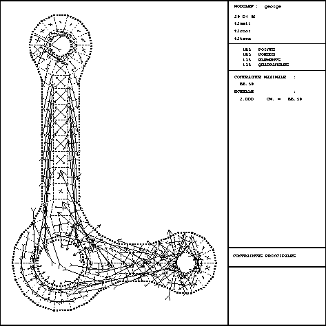
Figure 3.7: Example TRSTXX 2D: mesh and principal stresses
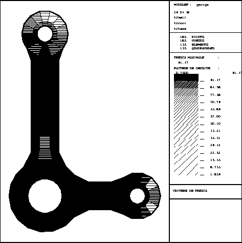
Figure 3.8: Example TRSTXX 2D: mesh and stresses (Tresca's criterion)
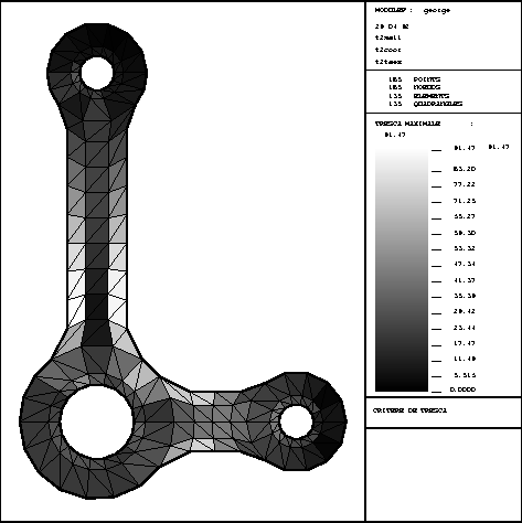
Figure 3.9: Example TRSTXX 2D: stresses (Tresca's criterion) with shading
In the case of an elasticity problem, we return to the above case by choosing options 4 or 5 in key 33. The user then needs to indicate, depending on the type of plasticity chosen, the values for the plasticity threshold (4) via key 43, or the frictional angle and cohesion coefficient (5) via key 43.
Activate key 10 and choose option 2. It is then necessary to enter the name of the file containing D.S. TAE containing the temperatures. The enlarged menu (additional keys indicated with an asterisk) is given below:
Activate key 10 and choose option 3. It is then necessary to enter the name of the file containing D.S. TAE containing the flux. The enlarged menu (additional keys indicated with an asterisk) is given below: