Next: 4 Visualization of curves Up: 3 Visualization of solutions Prev: 3.3 Two-dimensional stresses TRSTXX Contents
![]()
![]()
![]()
![]()
![]()
![]()
![]()
![]()
Next: 4 Visualization of curves
Up: 3 Visualization of solutions
Prev: 3.3 Two-dimensional stresses TRSTXX
Contents
Preprocessor TRC3XX is used to visualize meshes and the corresponding solutions.
The first part of this description recollects the different notions necessary for a good understanding of the operations performed when visualizing a three-dimensional mesh and solution.
The module computes the extrema corresponding to the mesh and solution automatically. These extrema is used to define the corners of the box in which the plot will be displayed.
The observation conditions of a three-dimensional mesh are defined in the same manner as for TRNOXX, to which the reader is referred.
The automatic visualization mode corresponds to a default choice of  ,
,  and
and  . In manual mode, the
user indicates:
 , the elevation
  and the span
  , or
, or
 and the observation point
  (in Cartesian coordinates).
The type of observation mode and corresponding parameters are displayed in the menu (keys 15 and 16, or keys 15, 17 and 18). Once a plot has been displayed, the two sets of parameters are indicated and the user can easily change from one observation mode to another.
In the three-dimensional case, the readability of a plot is closely related to the manner in which it is plotted. There are several types of plots:
The notion of visibility is interpreted differently according to the capabilities of the terminal used.
For a terminal without selective deletion,
an edge is called visible if the normal of the face to which it
belongs is directed towards the observation point
 . This simple algorithm presents some imperfections. For more advanced terminals, it is replaced by a
a "painter" type algorithm:
the faces are sorted and then plotted by starting by those furthest off, so that only those faces that are not hidden
by the closer up faces are visible on the plot.
A three-dimensional mesh can be displayed by plotting:
The faces can be colored-in, or not.
The general menu of TRMC3G (module called in this case) is given below.
-------------------------------------------------------------
 | 10 | PLOT TYPE                 |  MESH ONLY
 ------------------------------------------------------------
 | 11 | DEVICE NUMBER             |       1
 ------------------------------------------------------------
 | 12 | PLOT TITLE                |
 ------------------------------------------------------------
 | 15 | OBSERVATION MODE           | LONGITUDE/OX LATITUDE  APERTURE
 ------------------------------------------------------------
 | 16 | LONGIT. LATIT.  APERTURE  | 30.00000  30.00000  10.00000
 ------------------------------------------------------------
 | 88 | STEREO VISION             |   NO
 ------------------------------------------------------------
 | 20 | D.S. MAIL TO PLOT         |  amin2.mail
 ------------------------------------------------------------
 | 20 | D.S. COOR TO PLOT         |  amin2.coor
 ------------------------------------------------------------
 | 31 | QUESTIONS ABOUT A D.S.    |   NO
 ------------------------------------------------------------
 | 30 | PLOT SIZE                 |  AUTO
 ------------------------------------------------------------
 | 40 | CHARACTER TYPE            |  HARD
 ------------------------------------------------------------
 | 50 | ITEMS TO PLOT             |  OUTER SURFACE EDGES (ALL)
 ------------------------------------------------------------
 | 51 | COPLANAR EDGES            |  ELIMINATED
 ------------------------------------------------------------
 | 53 | COPLANARITY CRITERION     |    0.1000000E-04
 ------------------------------------------------------------
 | 54 | COLOUR-IN FACES           |   COLOUR-IN FACES
 ------------------------------------------------------------
 | 56 | FACE ORIENTATION          |  ORIENTED
 ------------------------------------------------------------
 | 60 | LEGEND                    |  YES
 ------------------------------------------------------------
 | 70 | NUMBER                    |  NONE
 ------------------------------------------------------------
 | 80 | LINE TYPE (MESH)          |  SOLID
 ------------------------------------------------------------
A default value is proposed for each option. We only visualize the mesh by default. To view a solution, we need to select key 10. The above table lists the choices made automatically. To obtain the corresponding plot, type 0.
A key (number) and status corresponds to each item. To modify the status, it suffices to type the key and enter (see general introduction) the values corresponding to the desired state. The list of keys is given below:
 and
and  (by default
30, 30 and 10 degrees respectively). To modify these values, type the key number and enter the new values.
    -- INITIAL MESH
       NOTHING (CHECK ONLY)      : 0
    ** SURFACE EDGES (ALL)       : 1
       SURFACE EDGES (VISIBLE)   : 2
       SURFACE EDGES (INVISIBLE) : 3
       SHRINK SURFACE (ALL FACES): 4
       SHRINK SURFACE (SEEN FACES): 5
       SHRINK SURFACE (HIDDEN F.): 6
    ** ALL ELEMENTS              : 7
       ALL SHRINKED ELEMENTS     : 8 ?
    NO NUMBER     : 0
    ELEMENT : 1 - NODE  : 3
    SUB-DOMAIN         : 4
    REFERENCE (ALL)    : 5
    REFERENCE NODES    : 7
    REFERENCE EDGES    : 8 - FACES : 9
    SOLID      : 1  --   DOTTED    : 2
    DASHED     : 3  --   MIXED     : 4 ?
Once a plot is displayed on the screen, a graphics menu appears which allows us to:
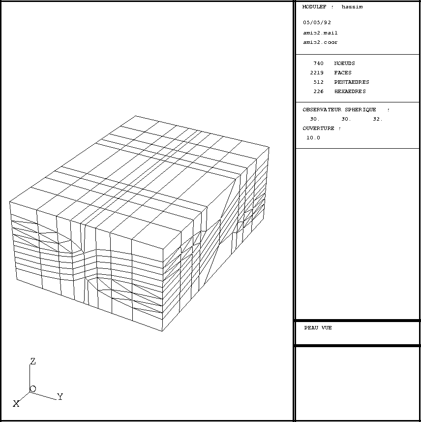
Request first a plot of the mesh (see above). The menu is as indicated above. The plot example given corresponds to the following sequence:

Figure 3.10: Example TRC3XX 3D: mesh, seen faces
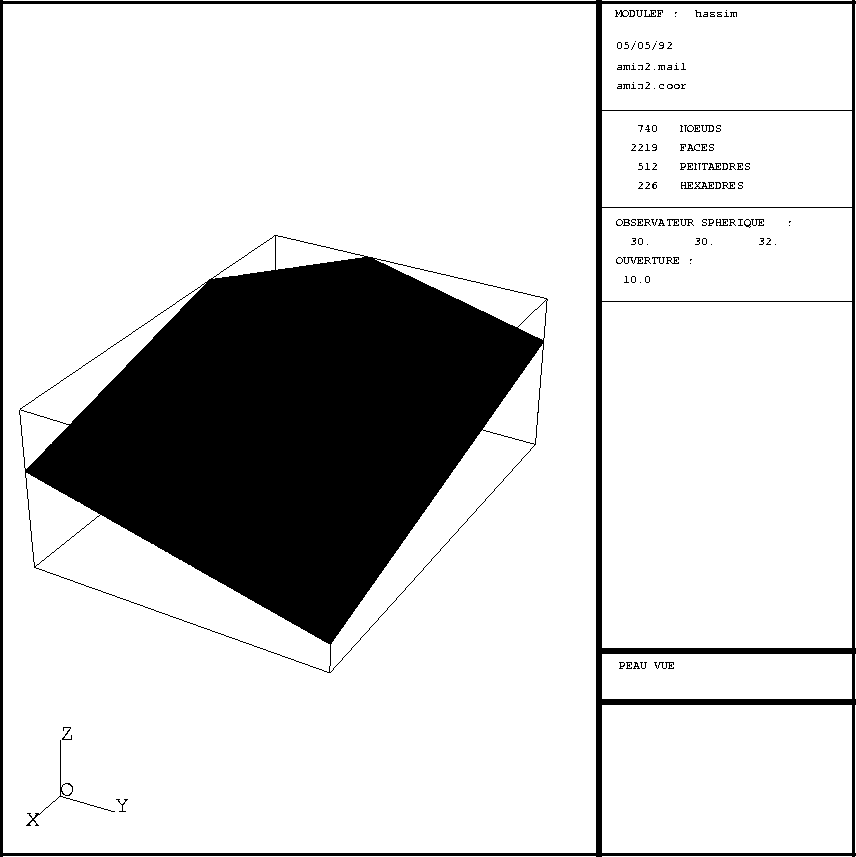
Departing from the plot displayed we then define a cut via the graphics menu to obtain a plot shown in figure 3.11, in which the cut plane is displayed, by inputting the following data:

Figure 3.11: Example TRC3XX 3D: cut through the above mesh
Activate key 10 and choose option 1. it is then necessary to input the name of the file containing D.S. B containing the solutions (displacements or velocities interpreted as displacements). The enlarged menu (additional keys indicated with an asterisk) is given below.
 ------------------------------------------------------------
 | 10 | PLOT TYPE                 |  MESH AND DEFORMATION
 ------------------------------------------------------------
 | 11 | DEVICE NUMBER             |       1
 ------------------------------------------------------------
 | 12 | PLOT TITLE                |
 ------------------------------------------------------------
 | 15 | OBSERVATION MODE           | LONGITUDE/OX LATITUDE  APERTURE
 ------------------------------------------------------------
 | 16 | LONGIT. LATIT.  APERTURE  | 30.00000   30.00000   10.00000
 ------------------------------------------------------------
 | 88 | STEREO VISION             |   NO
 ------------------------------------------------------------
 | 20 | D.S. MAIL TO PLOT         |  amin2.mail
 ------------------------------------------------------------
 | 20 | D.S. COOR TO PLOT         |  amin2.coor
 ------------------------------------------------------------
 | 21 | S.D. B USED               |  amin2.b
 ------------------------------------------------------------
 | 24 | LOAD CASE                 |       1
 ------------------------------------------------------------
 | 27 | TABLE B4 SELECTED         |       1
 ------------------------------------------------------------
 | 22 | DEFORMATION RATIO         |     100.0000
 ------------------------------------------------------------
 | 31 | QUESTIONS ABOUT A D.S.    |   NO
 ------------------------------------------------------------
 | 30 | PLOT SIZE                 |  AUTO
 ------------------------------------------------------------
 | 40 | CHARACTER TYPE            |  HARD
 ------------------------------------------------------------
 | 50 | ITEMS TO PLOT             |  OUTER SURFACE EDGES (ALL)
 ------------------------------------------------------------
 | 50 | ITEMS TO PLOT (DEFORM)    |  OUTER SURFACE EDGES (ALL)
 ------------------------------------------------------------
 | 51 | COPLANAR EDGES            |  ELIMINATED
 ------------------------------------------------------------
 | 52 | COPLANAR EDGES (DEFORMED) |  ELIMINATED
 ------------------------------------------------------------
 | 53 | COPLANARITY CRITERION     |    0.1000000E-04
 ------------------------------------------------------------
 | 54 | COLOUR-IN FACES           |   COLOUR-IN FACES
 ------------------------------------------------------------
 | 56 | FACE ORIENTATION          |  ORIENTED
 ------------------------------------------------------------
 | 60 | LEGEND                    |  YES
 ------------------------------------------------------------
 | 70 | NUMBER                    |  NONE
 ------------------------------------------------------------
 | 80 | LINE TYPE (MESH)          |  SOLID
 ------------------------------------------------------------
 | 80 | LINE TYPE (DEFORMATION)   |  SOLID
 ------------------------------------------------------------
A default value is proposed for each option. The above table lists the selections made automatically when plotting deformations. Type 0 to obtain the plot.
A key (a number) and a status correspond to each item. To modify the status, it suffices to type the key and enter the values corresponding to the status desired (see the general introduction). The list of keys is given below:
    SOLID      : 1  --   DOTTED    : 2
    DASHED     : 3  --   MIXED     : 4 ?
Once a plot is displayed on the screen, a graphics menu appears, as for the other modules, which allows us to execute operations (0), (1), (2), (3), (4), (5), (P T E Q), (C), (8) and (9) already present for a plot of a mesh only.
Activate key 10 and choose option 2. It is then necessary to enter the name of the file containing D.S. B containing the solutions. The enlarged menu (additional keys are indicated by an asterisk) is given below:
 -------------------------------------------------------------
 | 10 | PLOT TYPE                 |  MESH AND ISOVALUES
 -------------------------------------------------------------
 | 11 | DEVICE NUMBER             |       1
 -------------------------------------------------------------
 | 12 | PLOT TITLE                |
 -------------------------------------------------------------
 | 15 | OBSERVATION MODE          | LONGITUDE/OX LATITUDE  APERTURE
 -------------------------------------------------------------
 | 16 | LONGIT. LATIT.  APERTURE  |  30.00000  30.00000  10.00000
 -------------------------------------------------------------
 | 88 | STEREO VISION             |   NO
 -------------------------------------------------------------
 | 20 | D.S. MAIL TO PLOT         |  amin2.mail
 -------------------------------------------------------------
 | 20 | D.S. COOR TO PLOT         |  amin2.coor
 -------------------------------------------------------------
 | 21 | S.D. B USED               |  amin2.b
 -------------------------------------------------------------
 | 24 | LOAD CASE                 |       1
 -------------------------------------------------------------
 | 27 | TABLE B4 SELECTED         |       1
 -------------------------------------------------------------
 | 32 | UNKNOWN CHOSEN            |       1
 -------------------------------------------------------------
 | 32 | MNEMONIQUE CHOSEN         |  VN
 -------------------------------------------------------------
 | 25 | NUMBER OF ISOVALUES       |      20
 -------------------------------------------------------------
 | 26 | CHOICE FOR ISOVALUES      |   MIN < ** < MAX
 -------------------------------------------------------------
 | 72 | ISOVALUES PLOT            |   COLOUR LINE
 -------------------------------------------------------------
 | 35 | REPRESENT ISOVALUES       |   ON THE SURFACE
 -------------------------------------------------------------
 | 45 | COLOUR SPECTRUM IN USE    |   STANDARD : RED -> BLUE
 -------------------------------------------------------------
 | 46 | SPECTRUM DIRECTION        |   DIRECT
 -------------------------------------------------------------
 | 34 | COLOR-VALUE IMPOSED       |   YES
 -------------------------------------------------------------
 | 71 | ISOVALUES ARE POINTED     |   NO
 -------------------------------------------------------------
 | 31 | QUESTIONS ABOUT A D.S.    |   NO
 -------------------------------------------------------------
 | 30 | PLOT SIZE                 |  AUTO
 -------------------------------------------------------------
 | 40 | CHARACTER TYPE            |  HARD
 -------------------------------------------------------------
 | 50 | ITEMS TO PLOT             |  OUTER SURFACE EDGES (ALL)
 -------------------------------------------------------------
 | 51 | COPLANAR EDGES            |  ELIMINATED
 -------------------------------------------------------------
 | 53 | COPLANARITY CRITERION     |    0.1000000E-04
 -------------------------------------------------------------
 | 54 | COLOUR-IN FACES           |   COLOUR-IN FACES
 -------------------------------------------------------------
 | 56 | FACE ORIENTATION          |  ORIENTED
 -------------------------------------------------------------
 | 60 | LEGEND                    |  YES
 -------------------------------------------------------------
 | 70 | NUMBER                    |  NONE
 -------------------------------------------------------------
 | 80 | LINE TYPE (MESH)          |  SOLID
 -------------------------------------------------------------
 | 80 | LINE TYPE (ISOVALUES)     |  SOLID
 -------------------------------------------------------------
A default value is proposed for each option. The above table lists the selections made automatically when plotting the isovalues. Type 0 to obtain the plot.
A key (a number)and a status correspond to each item. To modify the status, it suffices to type the key and enter the values corresponding to the status desired (see the general introduction). The list of keys is given below:
   CHOICE OF REPRESENTATION:
     -1 : FIXED COLOUR LINE
      0 : COLOUR LINE
      1 : COLOURED-IN
   SPECTRUM ON 8 PLANE MONITORS :
   STANDARD  : RED TO BLUE           : 1
   RAINBOW   : RED TO MAGENTA        : 2
   THERMAL   : BLACK-RED-YELLOW-BLACK: 3
   MAXIMUM   : BLACK-COLOUR-WHITE    : 4
   BLACK AND WHITE                   : 5
    SOLID      : 1  --   DOTTED    : 2
    DASHED     : 3  --   MIXED     : 4 ?
and for the isovalues (for a plot of lines without markings) with the same choice.
Once a plot is displayed on the screen, a graphics menu appears, as for the other modules, which allows us to:
The only new feature is the item to obtain the value of an isovalue. There are several ways of performing this interrogation. One way corresponds to typing the letter and clicking on the isovalue under consideration, as for the two-dimensional case (see TRMCXX).
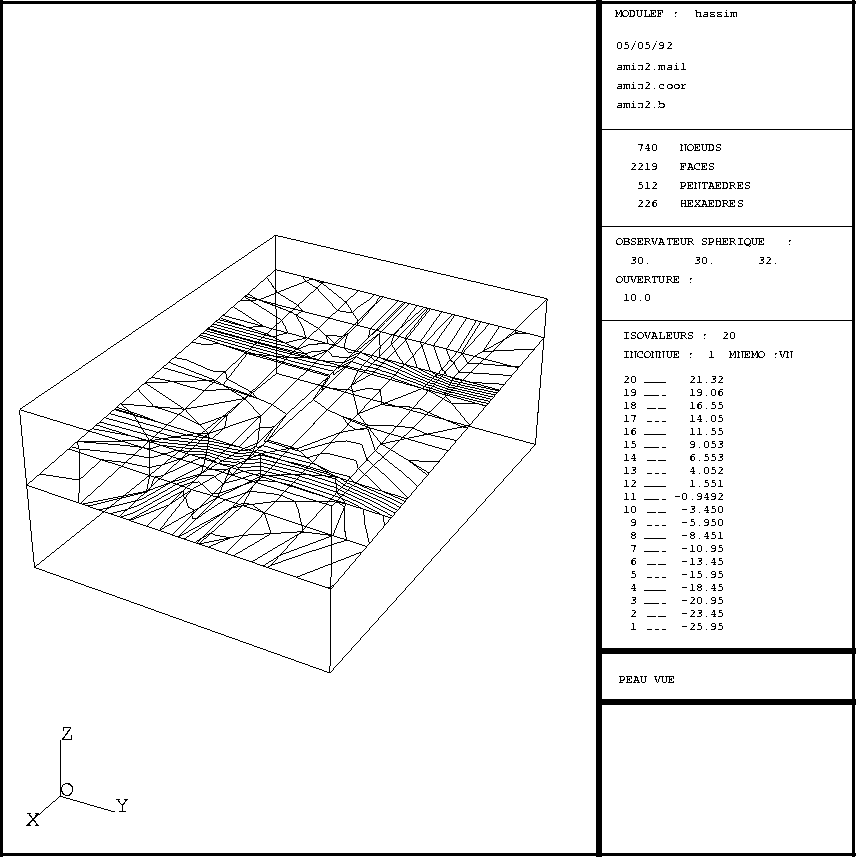
The plots were obtained by typing the following sequences:

Figure 3.12: Example TRC3XX 3D: Mesh and isovalues

Figure 3.13: Example TRC3XX 3D: Isovalues on a cut
Activate key 10 and choose option 3. It is then necessary to enter the name of the file containing the D.S. B containing the velocities. The enlarged menu is shown below:
 -------------------------------------------------------------
 | 10 | PLOT TYPE                 |  MESH AND VELOCITY
 -------------------------------------------------------------
 | 11 | DEVICE NUMBER             |       1
 -------------------------------------------------------------
 | 12 | PLOT TITLE                |
 -------------------------------------------------------------
 | 15 | OBSERVATION MODE          | LONGITUDE / OX  LATITUDE  APERTURE
 -------------------------------------------------------------
 | 16 | LONGIT. LATIT.  APERTURE  | 30.00000    30.00000    10.00000
 -------------------------------------------------------------
 | 88 | STEREO VISION             |   NO
 -------------------------------------------------------------
 | 20 | D.S. MAIL TO PLOT         |  amin2.mail
 ------------------------------------------------------------
 | 20 | D.S. COOR TO PLOT         |  amin2.coor
 ------------------------------------------------------------
 | 21 | S.D. B USED               |  amin2.b
 ------------------------------------------------------------
 | 24 | LOAD CASE                 |       1
 ------------------------------------------------------------
 | 27 | TABLE B4 SELECTED         |       1
 ------------------------------------------------------------
 | 29 | BIGEST ARROW IN CM.       |     2.000000
 ------------------------------------------------------------
 | 28 | ARROW ENDS                |       1
 ------------------------------------------------------------
 | 41 | TRANSPARENCY              |   NO
 ------------------------------------------------------------
 | 36 | ARROWS PLOTTED            |   YES
 ------------------------------------------------------------
 | 31 | QUESTIONS ABOUT A D.S.    |   NO
 ------------------------------------------------------------
 | 30 | PLOT SIZE                 |  AUTO
 ------------------------------------------------------------
 | 40 | CHARACTER TYPE            |  HARD
 ------------------------------------------------------------
 | 50 | ITEMS TO PLOT             |  OUTER SURFACE EDGES (ALL)
 ------------------------------------------------------------
 | 51 | COPLANAR EDGES            |  ELIMINATED
 ------------------------------------------------------------
 | 53 | COPLANARITY CRITERION     |    0.1000000E-04
 ------------------------------------------------------------
 | 54 | COLOUR-IN FACES           |   COLOUR-IN FACES
 ------------------------------------------------------------
 | 56 | FACE ORIENTATION          |  ORIENTED
 ------------------------------------------------------------
 | 60 | LEGEND                    |  YES
 ------------------------------------------------------------
 | 70 | NUMBER                    |  NONE
 ------------------------------------------------------------
 | 80 | LINE TYPE (MESH)          |  SOLID
 ------------------------------------------------------------
 | 80 | LINE TYPE (ARROWS)        |  SOLID
 ------------------------------------------------------------
A default value is proposed for each option. The above table lists the selections made automatically when plotting the stresses. Type 0 to obtain a plot of the mesh.
A key (a number) and a status corresponds to each item. To modify the status, it suffices to type the key and enter the values corresponding to the status desired (see the general introduction). The list of keys is given below:
   EXTREMITY OPEN , NORMALISED    : -1
   EXTREMITY CLOSED , NORMALISED  :  1
   EXTREMITY OPEN , FIXED         : -2
   EXTREMITY CLOSED , FIXED       :  2
The arrowhead is open (2 lines) or closed (a triangle), and its "length" is calculated as a function of the size of the arrow (which is related to the velocity modulus) or fixed (for all the arrows) to a value specified by the user.
    SOLID      : 1  --   DOTTED    : 2
    DASHED     : 3  --   MIXED     : 4 ?
Once a plot is displayed on the screen, a graphics menu appears, as for the other modules, which allows us to execute operations (0), (1), (2), (3), (4), (5), (6), (P T E Q), (7 X A Z), (8) and (9) already described.
The only new feature is the item to obtain the value of a velocity. There are several ways of performing this interrogation.One way corresponds to typing the letter and clicking on the isovalue under consideration, as for the two-dimensional case (see TRMCXX).
The cuts are obtained directly by using the graphics menu.
When plotting the isovalues of a solution it is necessary to define exactly what we want to plot. The finite elements used (described in D.S. MAIL) can be more, or less, rich (as a function of the degree of interpolation chosen).
The plot program is purely P1 and applies to the case of a triangular type element. Using the solution values at the three vertices of the triangle, the isovalues present in the triangle are calculated.
Consequently, each finite element must be decomposed into the most judicious set of triangles such that the quality of the interpolation is preserved: it does not correspond to making beautiful plots but plots conforming to known information. The decomposition must therefore satisfy this concern. It corresponds thus to interpreting each element in terms of P1 triangles.
For the three-dimensional case, program RANPQ3 decomposes the triangles and quadrilaterals (plot of the 3D finite elements on the visualization plane) into triangles.
Subroutine RANPQ3 uses a certain number of element subroutines. To add a finite element corresponds to adding the appropriate branch and using the appropriate element subroutine or writing a new one (each one very simple). To govern the computation, we have at our disposal the geometric code, the number of points and nodes and the arrays containing the points and nodes for the present element (it seems that with this information we are able to recognize all the elements without ambiguity).