Next: 7 Implementation notes Up: 6 Diverse visualizations Prev: 6.4 Characteristic points and lines TRPOXX Contents
![]()
![]()
![]()
![]()
![]()
![]()
![]()
![]()
Next: 7 Implementation notes
Up: 6 Diverse visualizations
Prev: 6.4 Characteristic points and lines TRPOXX
Contents
In the case of a 3D problem modeled using Lagrange elements of degree 1 (tetrahedron, pentahedron or hexahedron) for which the mesh is known in the form of a NOPO structure and the solution is a B structure, preprocessor COUPXX is used to plot the isovalues of the solution on a cut plane.
In practice, using preprocessor COUPXX, the user indicates to the module the different choices made from the possibilities offered.
The module computes the extrema corresponding to the mesh and solution automatically so that the corners of the box in which the plot will be displayed can be defined.
The menu of TRISO3 (module called in this case) is shown below:
 ------------------------------------------------------------
 |    | PLOT TYPE                 |  MESH AND CUT OF A 3D D.S. B
 ------------------------------------------------------------
 | 20 | D.S. NOPO IN USE          |  levier.nopo
 ------------------------------------------------------------
 | 20 | S.D. B IN USE             |  levier.b
 ------------------------------------------------------------
 | 21 | PLANE : AX+BY+CZ+D=0.     |      1.0000             0.00000
 ------------------------------------------------------------
 | 21 |                           |     0.00000              1.0000
 ------------------------------------------------------------
 | 24 | LOAD CASE                 |       1
 ------------------------------------------------------------
 | 27 | TABLE B4 IN USE           |       1
 ------------------------------------------------------------
 | 28 | TIMESTEP TO BE USED       |   NOT USED
 ------------------------------------------------------------
 | 32 | D.O.F. IN USE             |       1
 ------------------------------------------------------------
 | 25 | NUMBER OF ISOVALUES       |      20
 ------------------------------------------------------------
 | 26 | CHOICE FOR ISOVALUES      |   MIN < ** < MAX
 ------------------------------------------------------------
 | 71 | ISOVALUES ARE POINTED     |   NO
 ------------------------------------------------------------
 | 31 | QUESTIONS ABOUT A D.S.    |   NO
 ------------------------------------------------------------
 | 30 | PLOT SIZE                 |  AUTO
 ------------------------------------------------------------
 | 40 | CHARACTER TYPE            |  HARD
 ------------------------------------------------------------
 | 50 | ITEMS TO PLOT             |  TRIANGULATION
 ------------------------------------------------------------
 | 51 | SUB-DOMAINS CONSIDERED    |  ALL
 ------------------------------------------------------------
 | 52 | OVERLAPPING               |  YES
 ------------------------------------------------------------
 | 60 | LEGEND                    |  YES
 ------------------------------------------------------------
 | 80 | LINE TYPE (MESH)          |  SOLID
 ------------------------------------------------------------
 | 80 | LINE TYPE (ISOVALUES) |      DOTTED
 ------------------------------------------------------------
A default value is proposed for each option. The above table lists the selections made automatically when plotting the stresses. Type 0 to obtain the plot of the mesh.
A key (a number) and a status corresponds to each item. To modify the status, it suffices to type the key and enter the values corresponding to the status desired (see the general introduction). The list of keys is given below:
  -- MESH
     NOTHING                 : 0
     TRIANGULATION           : 1
     GEOMETRIC BOUNDARY      : 2
-- OTHER VIEW (YES-NO) ?a plot of the isovalues without the mesh.
    SOLID      : 1  --   DOTTED    : 2
    DASHED     : 3  --   MIXED     : 4 ?
and for the solution: DOTTED (by default) or, by activating the key the choice shown above.
Once a plot is displayed on the screen, a graphics menu appears which allows us to:
In the case of a 2D problem modeled using Lagrange elements of degree 1 for which the mesh is known in the form of a NOPO structure and the solution is a B structure, preprocessor ISOPXX is used to plot the isovalues (it corresponds to a poor version of TRMCXX). In reality, this preprocessor was written to visualize solutions (piezometric pressure and head) of an incompressible fluid flow problem in a porous medium.
In practice, using preprocessor ISOPXX, the user indicates to the module the different choices made from the possibilities offered.
The module computes the extrema corresponding to the mesh and solution automatically so that the corners of the box in which the plot will be displayed can be defined.
The menu of ISOPIE (module called in this case) is identical to that obtained for TRNOPO (module used to plot a 2D mesh, to which the user is referred) By activating key 10, we indicate that the solution must be considered after which the name of the file containing it must be entered. The enlarged menu is shown below;
 ------------------------------------------------------------
 | 10 | PLOT TYPE                 |  MESH AND ISOVALUES
 ------------------------------------------------------------
 | 11 | DEVICE NUMBER             |       1
 ------------------------------------------------------------
 | 12 | PLOT TITLE               |   piezo
 ------------------------------------------------------------
 | 20 | D.S. NOPO TO PLOT         |  damian.nopo
 ------------------------------------------------------------
 | 21 | S.D. B IN USE             |  damian.b
 ------------------------------------------------------------
 | 24 | LOAD CASE                 |       1
 ------------------------------------------------------------
 | 27 | ARRAY B4 SELECTED         |       1
 ------------------------------------------------------------
 | 28 | CLASSICAL PROBLEM         |
 ------------------------------------------------------------
 | 32 | D.O.F. CHOSEN             |       1
 ------------------------------------------------------------
 | 25 | NUMBER OF ISOVALUES       |      20
 ------------------------------------------------------------
 | 26 | ISOVALUE CHOICE           |   MIN < ** < MAX
 ------------------------------------------------------------
 | 72 | ISOVALUES PLOT            |   COLOUR LINE
 ------------------------------------------------------------
 | 45 | COLOR SPECTRUM            |   STANDARD : RED -> BLUE
 ------------------------------------------------------------
 | 46 | SPECTRUM DIRECTION        |   DIRECT
 ------------------------------------------------------------
 | 34 | COLOR-VALUE IMPOSED       |   NO
 ------------------------------------------------------------
 | 71 | ISOVALUES ARE POINTED     |   NO
 ------------------------------------------------------------
 | 31 | QUESTIONS ABOUT A D.S.    |   NO
 ------------------------------------------------------------
 | 30 | PLOT SIZE                 |  AUTO
 ------------------------------------------------------------
 | 40 | CHARACTER TYPE            |  HARD
 ------------------------------------------------------------
 | 50 | ITEMS TO PLOT             |  TRIANGULATION
 ------------------------------------------------------------
 | 60 | LEGEND                    |  YES
 ------------------------------------------------------------
 | 70 | NUMBER                    |  NONE
 ------------------------------------------------------------
 | 80 | LINE TYPE (MESH)          |  SOLID
 ------------------------------------------------------------
 | 80 | LINE TYPE (ISOVALUES)     |  SOLID
 ------------------------------------------------------------
A default value is proposed for each option. The above table lists the selections made automatically. Type 0 to obtain a plot.
A key (a number) and a status correspond to each item. To modify the status, it suffices to type the key and enter the values corresponding to the status desired (see the general introduction). The general initial menu is identical to that obtained when using TRNOXX in 2D. By choosing, via key 10, to plot a solution, the menu described below is obtained:
MESH : 0 -- ISOVALUES : 1
    PRESSURE              : 1
    PIEZOMETRIC HEAD      : 2
  -- MESH
     NOTHING                 : 0
     TRIANGULATION           : 1
     GEOMETRIC BOUNDARY      : 2
    SOLID      : 1  --   DOTTED    : 2
    DASHED     : 3  --   MIXED     : 4 ?
and the same choice for the isovalues.
Once a plot is displayed on the screen, a graphics menu appears, as for the other modules.
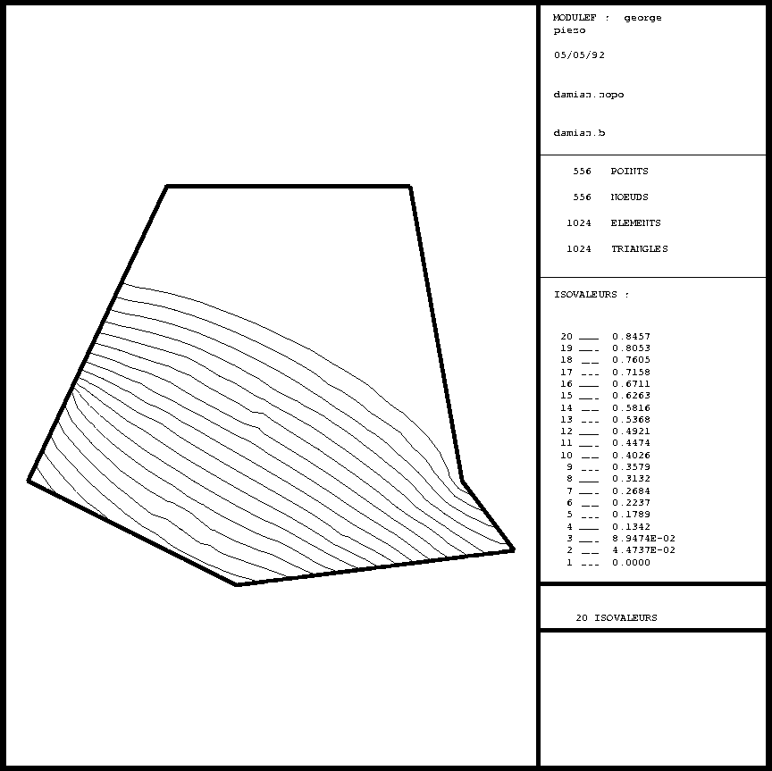
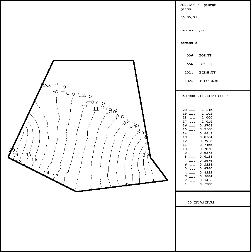
The plots were obtained by typing the following sequences:

Figure 6.4: Example ISOPXX: pressure

Figure 6.5: Example ISOPXX: piezometric head
To plot the eigenvalues of a problem, we use preprocessor CODEXX to constructs a file from D.S. VVPR which is read by TRACXX to visualize the eigenvalues.
To plot the eigenvectors of a problem, we use preprocessor COBVXX to construct a B structure from D.S. VVPR containing one or several vectors which is read by TRMCXX to visualize the eigenvectors in the form of a deformation or velocity.